concrete building Design Software
COMPREHENSIVE SOFTWARE SUITE FOR STRUCTURAL ENGINEERING
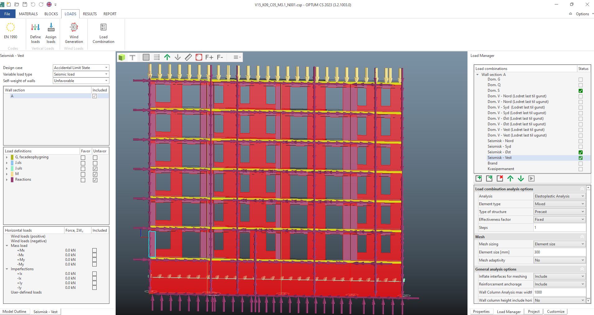
Perfect for comprehensive building analysis, OPTUM CS ensures your structures maintain their integrity, efficiently distribute loads, and remain stable under various conditions. It's your go-to solution for large-scale construction projects, offering unmatched precision in identifying critical stress points.
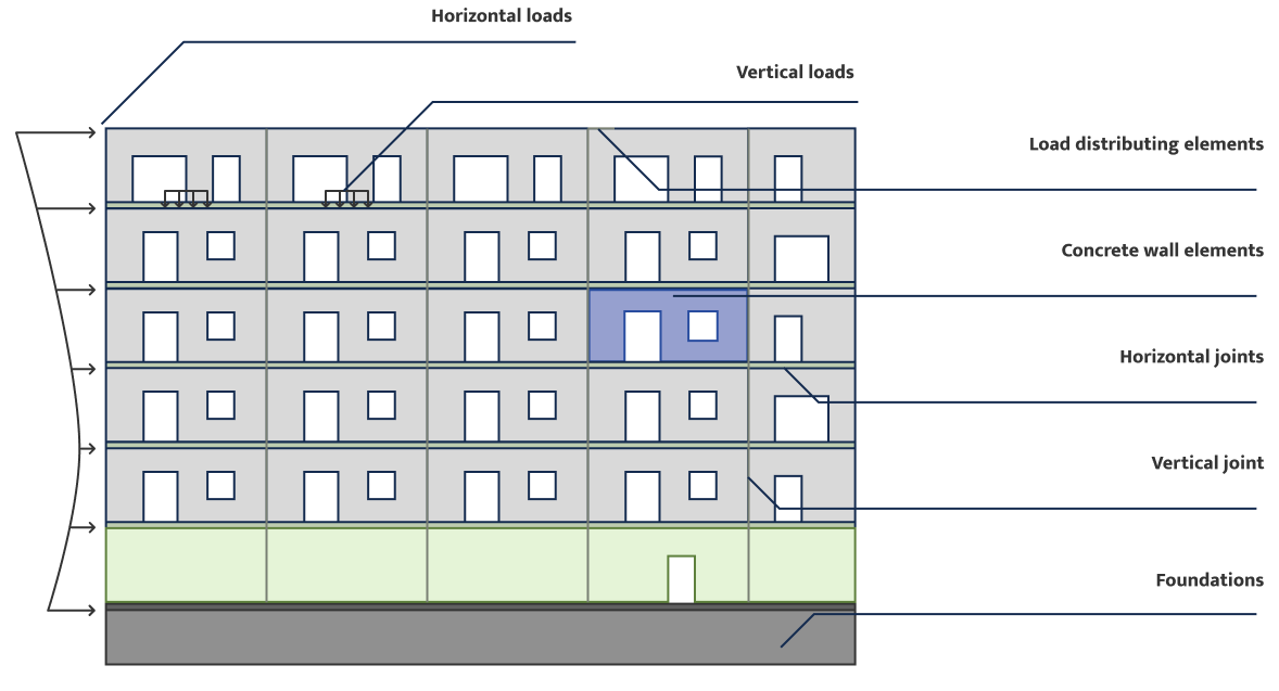
OPTUM SP our specialized Horizontal Load Calculation Software, focuses on accurately simulating and calculating horizontal forces such as wind, seismic activity, and lateral loads. These forces are crucial for ensuring the stability and safety of your structures.
Conduct Ultimate Limit State (ULS) and Serviceability Limit State (SLS) analyses of reinforced concrete slabs with OPTUM MP. This advanced tool is ideal for dealing with complex slab layouts, seeking efficient time and material utilization.


OPTUM CS

Material Savings: Achieve over 30% reduction in concrete
and reinforcement usage, translating to significant cost savings.- Time Efficiency: Streamline your workflow and reduce engineering hours with automatic report generation, allowing you to focus on what matters most.
- Environmental Impact: Contribute to substantial CO2 savings, aligning with sustainability goals and reduce your carbon footprint.
Certified Sustainability: Obtain sustainability certification for your concrete constructions, showcasing your commitment to
eco-friendly practices.- Eurocodes Compliance: Ensure full compliance with Eurocodes, meeting regulatory standards and industry requirements effortlessly.
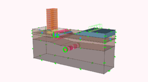
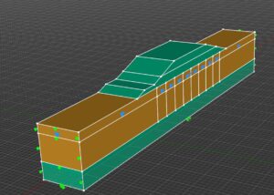
Automatic Load Transfer from struXML with Python
With the latest Python script – developed in collaboration with Sweco and Spæncom – you can now automatically generate complete CSP models in OPTUM CS directly from struXML files.
This provides significant advantages for both consulting engineers and element manufacturers involved in structural design:
- Automatic transfer of geometry, loads, and reactions
- Inclusion of load combinations, eccentricity, and special effects (e.g. fire loads or balcony fixings)
- Full compliance with equilibrium and interface conditions – no manual post-processing required
- Significantly faster design process
- No manual setup – reduced risk of errors
"It works seamlessly. We can now generate a complete CS model with both geometry and loads – saving a great deal of design time."
— Danny Hansen, Structural Engineer, Spæncom
"The new automation makes the process much more efficient and reduces the frustration of time-consuming manual work."
— Martin Bønnelykke, Structural Engineer, Sweco
FEa software package FOR REINFORCED CONCRETE SLAB DESIGN
Conduct Ultimate Limit State (ULS) and Serviceability Limit State (SLS) analyses of reinforced concrete slabs with OPTUM MP effortlessly. This advanced tool is ideal for consulting engineers dealing with complex slab layouts, seeking efficient time and material utilization.
OPTIMIZE your CONCRETE and reinforcement SLABS WITH stringer

OPTUM SP is a specialized Horizontal Load Calculation Software, and focuses on accurately simulating and calculating horizontal forces such as wind, seismic activity, and lateral loads. These forces are crucial for ensuring the stability and safety of your structures.
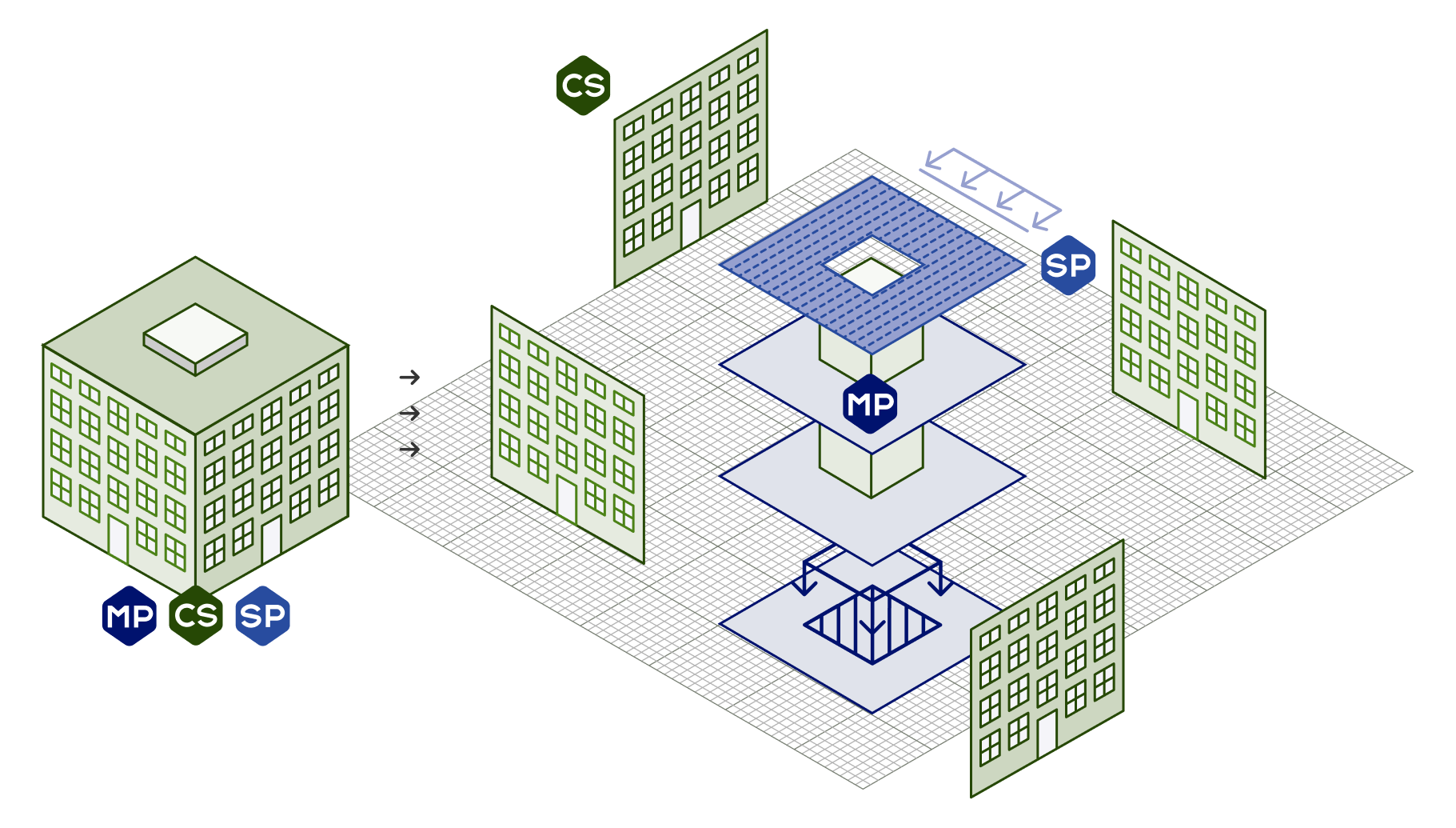
The OPTUM CS way vs. The Traditional Way

Optum Way
Uses Elastoplastic FEA to calculate
Use less reinforcement and concrete

1
Reinforcement

2
Loads

3
4
Post-processing According to ec2

Traditional Way
Uses Elasticplastic FEA to calculate
More reinforcement and concerete

1
Geometry

2
Loads

3
Elastic fe calculation stress distribution

4
Post-processing According to ec2 Reinforcement norm check
Elastoplastic Analysis
Enhanced Geometry and Initial Reinforcement: Starts with the geometry and initial reinforcement in place.
Comprehensive Stress Analysis: Considers both elastic and plastic material behavior, providing a more accurate stress distribution.
- Improved Compliance Check: Ensures reinforcement meets Eurocode 2 standards after accounting for plastic behavior, leading to more effective and safer structural designs.
Elastic Analysis
- Basic Geometry and Loads: Shows the structure's basic layout and applied loads.
Stress Distribution: Calculates how stresses are distributed under these loads.
Reinforcement Design: Determines necessary reinforcement based on stress distribution, following Eurocode 2 standards.
Key Benefits
- Accuracy: Elastoplastic analysis offers a more realistic assessment of structural behavior under loads.
Safety: By considering material plasticity, it provides a safer design with appropriate reinforcement.
Compliance: Ensures better adherence to building codes and standards, enhancing overall structural integrity.
In summary, elastoplastic analysis offers a deeper, more reliable understanding of structural performance, leading to safer, more compliant building designs.

Simplify Your Documentation Process with OPTUM CS
Automatic report generation minimizes manual effort, saving you valuable time while ensuring accuracy. Reports include comprehensive safety factors, stress and strain checks, built-in code compliance checks, and detailed post-processed results.
Pricing
Concrete building design package
Design strips for wall code check
Code check of beams and columns
Fire design included
Elastoplastic analysis for SLS and ULS
Automatic report generator

Shear walls and diaphragms analysis
Stringer and Limit Analysis for ULS
Elastoplastic analysis for SLS
Optimal plastic solution for slabs
Load manager based on Eurocode
Automatic report generator

Slab yield line analysis in seconds
Elastoplastic analysis for SLS
Safety factors according to EN1992
Load manager based on Eurocode
Include column
Automatic report generator
MAXIMIZE YOUR SOFTWARE INVESTMENT
In just one day, your engineers will gain a deep understanding of OPTUM GX, allowing for more efficient and seamless use. We recommend starting with a real project you're already working on. This makes the training highly relevant — and helps the software become part of your team’s everyday workflow from day one. The course is more than just onboarding. It’s an investment in your team’s professional development and the successful implementation of your software.
A small effort with a significant return.
Stay informed with Optum's newsletter!
Join our mailing list to be among the first to hear about:

Software updates

Webinars

Upcoming events

Special deals