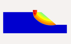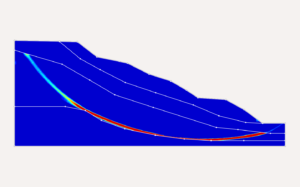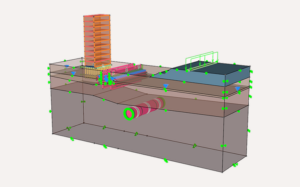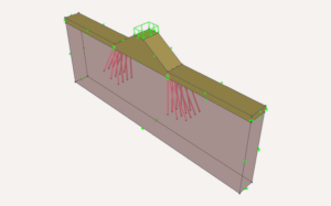
Determination of stability of slopes have been a major challenge Foundations built on or near hilly terrain do not behave like foundations on flat ground. The absence of confining soil on the downhill side, the possibility of a pre-existing failure surface passing beneath the footing, and the interaction between the foundation load and the overall slope stability all change the problem. A single bearing-capacity number, calculated in isolation from the slope it sits on, is rarely the full picture.
This article sets out a practical workflow for analysing and designing foundations on sloped ground using OPTUM GX — a geotechnical analysis platform built on the Finite Element Limit Analysis (FELA). Unlike workflows built around correlations from borehole logs and empirical bearing-capacity charts, OPTUM GX solves the foundation–slope system directly, computing the failure mechanism and the collapse load together rather than assuming one and calculating the other.
1. Why Slope Foundations Need a Different Approach
On level ground, bearing capacity is governed by a well-defined failure surface that develops symmetrically beneath the footing. On a slope, that surface is free to move toward the open, unsupported or unconfined side, following whatever path costs the least resistance through the soil. Three things follow from this:
- The effective bearing capacity is lower than the flat-ground value, and the reduction grows with slope angle, footing proximity to the crest, and footing embedment.
- The controlling failure mechanism may not be a local punching failure under the footing at all — it may be a shallow or deep-seated slope failure that happens to pass through the footing zone.
- Any check that treats “bearing capacity” and “slope stability” as two separate calculations risks missing the mechanism that governs the design.
2. Reason Where Conventional Methods Fall Short
The traditional route to a slope-foundation design combines two separate calculation families:
- Empirical bearing-capacity chart and tied to idealized geometries.
- Limit Equilibrium Method (LEM) slope-stability checks, in which the engineer pre-selects a shape for the failure surface (circular, wedge, or non-circular) and searches for the critical one within that assumed family.
Both routes carry the same underlying limitation:
“The shape of the failure mechanism is assumed before the analysis begins.”
If the true governing mechanism does not resemble the assumed shape — which is common with layered soils, benched footings, or irregular slope profiles — the calculated factor of safety can be misleading in either direction. LEM also does not directly output a full stress field, so settlement and deformation behaviour have to be estimated separately, often from a different tool altogether.
A useful analysis starts with the design decision that needs to be made. Typical questions are:
- Is the proposed footing location controlled by foundation bearing failure or by the adjacent slope?
- How does increasing the setback from the crest change the capacity and failure mechanism?
- Would a change in footing width, embedment or slope geometry materially improve the response?
- Is a 2D plane-strain idealization appropriate, or does the geometry require a 3D assessment?
- Will excavation, benching, filling or stabilization change the stress history and therefore the final response?
3. How OPTUM GX Works: FEM + LA with OBFEM
OPTUM GX is built on the Optimization-Based Finite Element Method (OBFEM), a solver that unifies two analysis types that are normally handled by separate programs:
Finite Element Limit Analysis (FELA): computes the true collapse load directly from plasticity theory, without incremental load stepping and without assuming a failure surface. Crucially, FELA delivers rigorous upper-bound and lower-bound solutions that bracket the exact collapse load — giving a built-in check on solution accuracy that classical FEM and LEM cannot offer.
Because both are solved within the same optimization-based framework, OPTUM GX does not suffer the convergence problems that affect classical elasto-plastic FEM at high load levels or near collapse. This matters specifically for slope-foundation problems, where the model is, by definition, being pushed toward a failure state to find the governing mechanism.
In practice this means one model can deliver:
- The ultimate bearing capacity of the footing accounting for the slope geometry,
- the governing failure mechanism — whether local punching, combined footing-slope failure, or a deep-seated slide, and
- settlement and stress redistribution under service loads — without switching software or re-building the geometry.
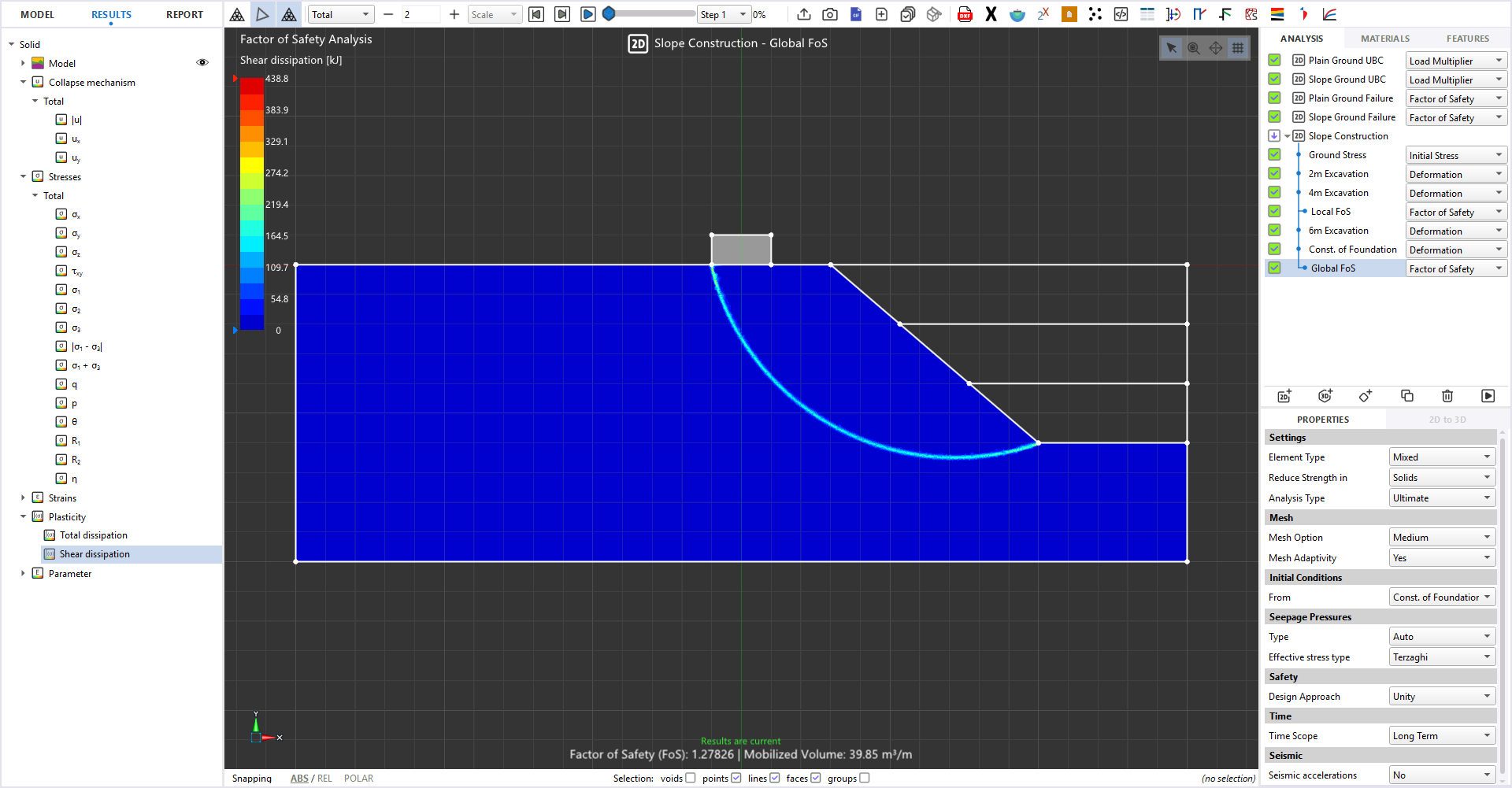
4. Setting Up a Slope-Foundation Model in OPTUM GX
The workflow below reflects how a foundation-on-slope problem is typically built up in OPTUM GX, from geometry to results. No borehole-log correlation step is required — soil parameters are entered directly as material model inputs, sourced from lab or in-situ test data.
4.1 Geometry and domain
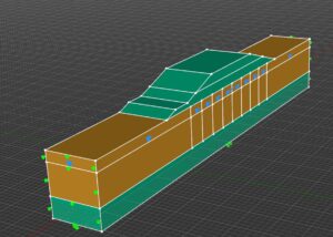
Define the slope profile (crest, face, toe, and any berms or benches) and the footing geometry — width, embedment depth, and setback distance from the crest — in 2D (plane strain) for a strip footing or long footing, or in 3D where the footing is finite in both plan directions or the slope geometry is genuinely three-dimensional (a re-entrant corner, a spur, or a localized embankment).
4.2 Material models and layering
Assign layered soil profiles using the appropriate constitutive model for the problem at hand — Mohr-Coulomb for a standard strength-governed check, or more advanced models (Hardening Soil, Modified Cam Clay) where stiffness-dependent settlement behaviour or stress-history effects matter. Non-associated flow (dilation angle less than friction angle) is supported directly, which is important because real soils rarely dilate at the same rate they shear.
4.3 Boundary conditions and staged construction
Set far-field and base boundary conditions sized to avoid boundary effects influencing the failure mechanism — a mechanism that clips the model boundary is a modelling error, not a result. Where the foundation is built after cutting or benching the slope, or where fill is placed in stages, the construction sequence is modelled stage-by-stage so that the stress history feeding into the final check is realistic rather than assumed.
4.4 Loading
Apply the footing load — vertical, or vertical plus eccentric/inclined where the superstructure imposes lateral or moment loading, which is common on sloped sites with retaining elements or asymmetric structures.
4.5 Mesh and adaptivity
OPTUM GX supports automatic adaptive mesh refinement, concentrating elements around the zone where the failure mechanism is developing rather than requiring the engineer to guess where refinement is needed in advance.

Geometry
Define the slope, crest, toe/bench geometry and footing width, length, embedment and setback.

Materials
Define the slope, crest, toe/bench geometry and footing width, length, embedment and setback.

Construction
Define the slope, crest, toe/bench geometry and footing width, length, embedment and setback.

Loading
Define the slope, crest, toe/bench geometry and footing width, length, embedment and setback.

Analysis
Define the slope, crest, toe/bench geometry and footing width, length, embedment and setback.

Verification
Define the slope, crest, toe/bench geometry and footing width, length, embedment and setback.
5. Reading the Results: Bearing Capacity, Mechanisms, Settlement
A completed run returns several linked outputs that should be read together, not in isolation:
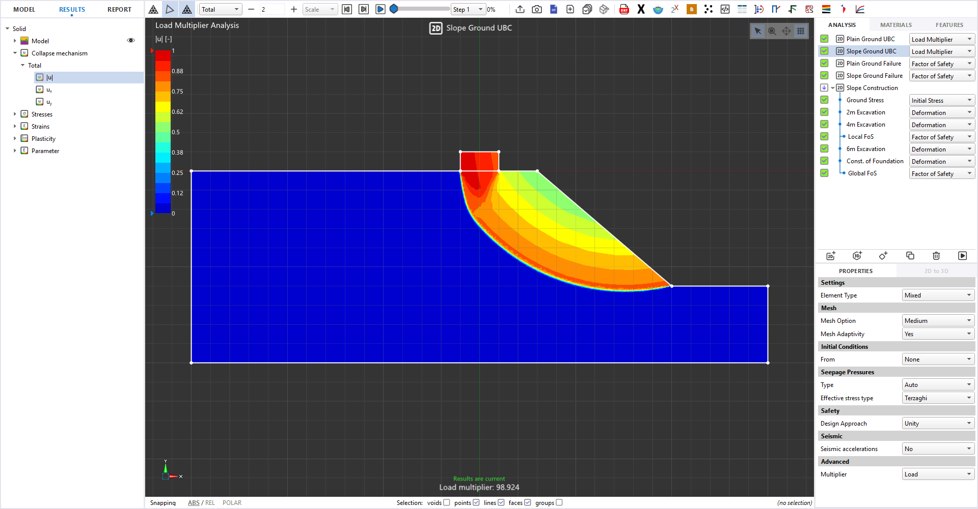
- Bound gap on the collapse load: the numerical difference between the FELA upper and lower bound. A tight bound gap is the direct, built-in indicator that the mesh and model are adequate — there is no need for a separate convergence study of the kind classical FEM requires.
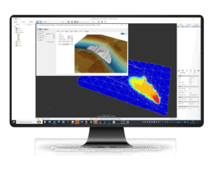
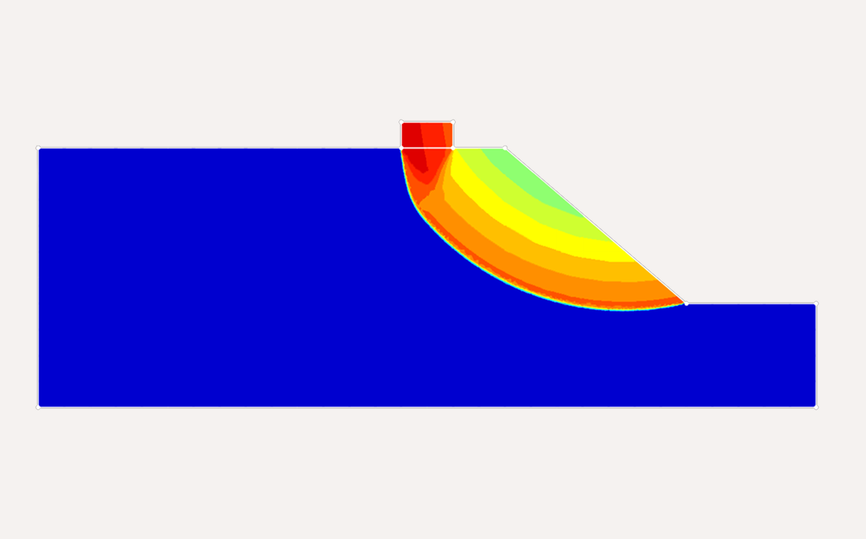
- Governing failure mechanism: shown as a shear-strain or velocity field. This is the step that tells the engineer whether the design is limited by local bearing failure under the footing or by a wider slope mechanism that happens to pass through the loaded zone — the distinction that conventional decoupled methods can obscure.
- Displacement and settlement contours: from the FEM/strength-reduction stage, giving working-load deformation behaviour for serviceability checks, including differential settlement across a benched or stepped foundation.
- Safety factor mapping: where multiple potential mechanisms exist across a slope, Python-scripted batch runs can generate a safety-factor map across the site rather than a single number at one location.
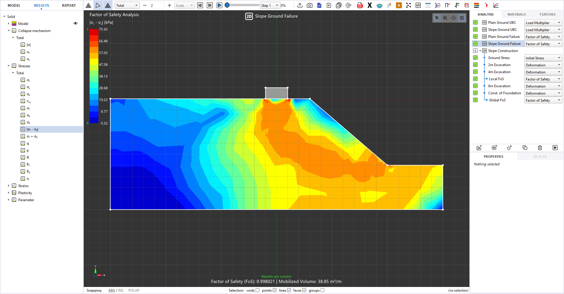
6. Design Considerations Specific to Sloped Sites
A single model gives a result for one configuration. For hillside foundations, a small number of targeted alternative models is often more informative because the objective is usually to decide how the foundation or slope should be modified.
A compact study can investigate:
- Setback from the crest — identify whether capacity continues to improve and whether the failure mechanism changes.
- Slope angle — assess the sensitivity of the foundation response to the available soil confinement.
- Footing width and embedment — examine whether geometry changes alter the governing mechanism.
- Loading — consider eccentric or inclined loading where it represents the actual structural load path.
- Stabilization — where retaining, reinforcement, piles or other measures are part of the design, assess their interaction with the foundation system.
The objective is not to generate many cases. A small, well-selected set of models can show the transition from a slope-controlled mechanism to a foundation-controlled mechanism and support a practical design choice.
- Setback distance from the crest: increasing setback is usually the single most effective way to raise bearing capacity on a slope; the model should be re-run at a small number of setback options to find the point of diminishing return, rather than applying a single blanket rule.
- Benching and stepped footings: where a uniform setback is not practical, staged excavation into the slope with stepped footing levels needs the construction sequence modelled explicitly, since the stress path — not just the final geometry — affects the outcome.
- Seepage and pore pressure: slopes with seasonal groundwater fluctuation should be checked under the pore-pressure condition that is actually governing (often not the driest case), using coupled seepage-deformation analysis rather than a single assumed water table.
- Eccentric and inclined loading: superstructure loads transmitted with a lateral or moment component reduce the effective bearing capacity further and should be modelled as such, not simplified to a vertical-only load.
- Interaction with retaining or slope-stabilization elements: where soil nails, piles, or a retaining wall are part of the same system, they should be included in the same model so the load path between foundation and stabilization measure is captured rather than assumed independent.
7. Verifying the Analysis: Bounds, Mesh, and Sanity Checks
Because FELA produces both an upper and a lower bound on the true collapse load, verification is largely built into the method itself: a narrow bound gap after adaptive refinement is direct evidence that the computed capacity is close to the exact solution, independent of any external benchmark. Beyond that internal check, three practical habits are worth keeping:
- Confirm the failure mechanism does not intersect or clip the model boundaries — if it does, extend the domain and re-run.
- Cross-check an idealized sub-case (e.g., the same footing on level ground, slope angle set to zero) against a known closed-form bearing-capacity solution before trusting the sloped case.
- Where the project scale justifies it, validate the 2D plane-strain result against a 3D model to confirm that plane-strain is actually a reasonable simplification for the geometry in question — OPTUM GX's shared 2D/3D workflow makes this a direct comparison rather than a separate rebuild.
Conclusion
Foundations on hilly ground are, fundamentally, a coupled bearing-capacity and slope-stability problem, and treating them as two independent checks is where conventional workflows lose accuracy. A FEM + LA workflow, as implemented through OBFEM in OPTUM GX, removes the need to assume a failure-surface shape or lean on empirical slope-correction charts: the governing mechanism, the collapse load with verified bounds, and the working-load settlement behaviour all come from one consistent model. For engineers working on sloped or hillside sites, that combination — mechanism plus magnitude plus a built-in accuracy check — is the practical advantage over decoupled, assumption-driven methods.
References
Krabbenhoft, K. – OptumG2 / OPTUM GX Theory Manual, Optum Computational Engineering.
Krabbenhoft, K., and Lyamin, A.V. (2015). “Strength reduction finite-element limit analysis.” Géotechnique Letters, 5.


Developed for engineers
Backed by performance
Download your free trial of OPTUM GX geotechnical software. No credit card required.
Just fill out a short form and start modelling real-world designs — not assumptions.
Download Free Trial
Frequently ASked Questions
Can’t find what you’re looking for? Contact us here.

Designing and Analyzing Foundations on Hilly Slopes
October 7, 2026
Determination of stability of slopes have been a major challenge Foundations built on or near hilly terrain do not behave like foundations on flat ground. The absence of confining soil...
Geotechnical
OPTUM GX
Advanced Slope Stability Assessment through Reliability Analysis in OPTUM GX
August 4, 2026
Determination of stability of slopes have been a major challenge in geotechnical engineering. Slopes that pass through the rigours analysis often fail due to several on-site uncertainties making it a...
Geotechnical
OPTUM GX
What is Finite Element Analysis?
February 3, 2026
Finite element analysis (FEA) is a numerical method that breaks a complex structure into many small “elements” to predict how it responds to loads, deformation, temperature changes and other physical...
FEA
Finite element analysis
Geotechnical
OPTUM GX