Finite element analysis (FEA) is a numerical method that breaks a complex structure into many small “elements” to predict how it responds to loads, deformation, temperature changes and other physical effects.
If you’ve ever asked: “What is finite element analysis?”, the simplest answer is this: FEA helps engineers understand and predict real-world behaviour before anything is built.
By turning a physical system into a mathematical model, FEA enables safer designs, faster iterations and deeper insight across engineering disciplines — especially in geotechnical and civil engineering, where behaviour is highly nonlinear and difficult to idealise.
A Brief History of Finite Element Analysis
FEA emerged in the 1950s within the aerospace industry, where engineers needed a way to analyse complex aircraft structures. Early pioneers such as Turner, Clough and Zienkiewicz formalised the method and laid the foundation for computational mechanics.
With advances in computing in the 1970s–2000s, FEA expanded into civil, mechanical, automotive and geotechnical engineering. Today, modern solvers, high-performance computing and automated workflows allow engineers to run advanced simulations in minutes — not days.
How FEA Works in Geotechnics: Step-by-Step
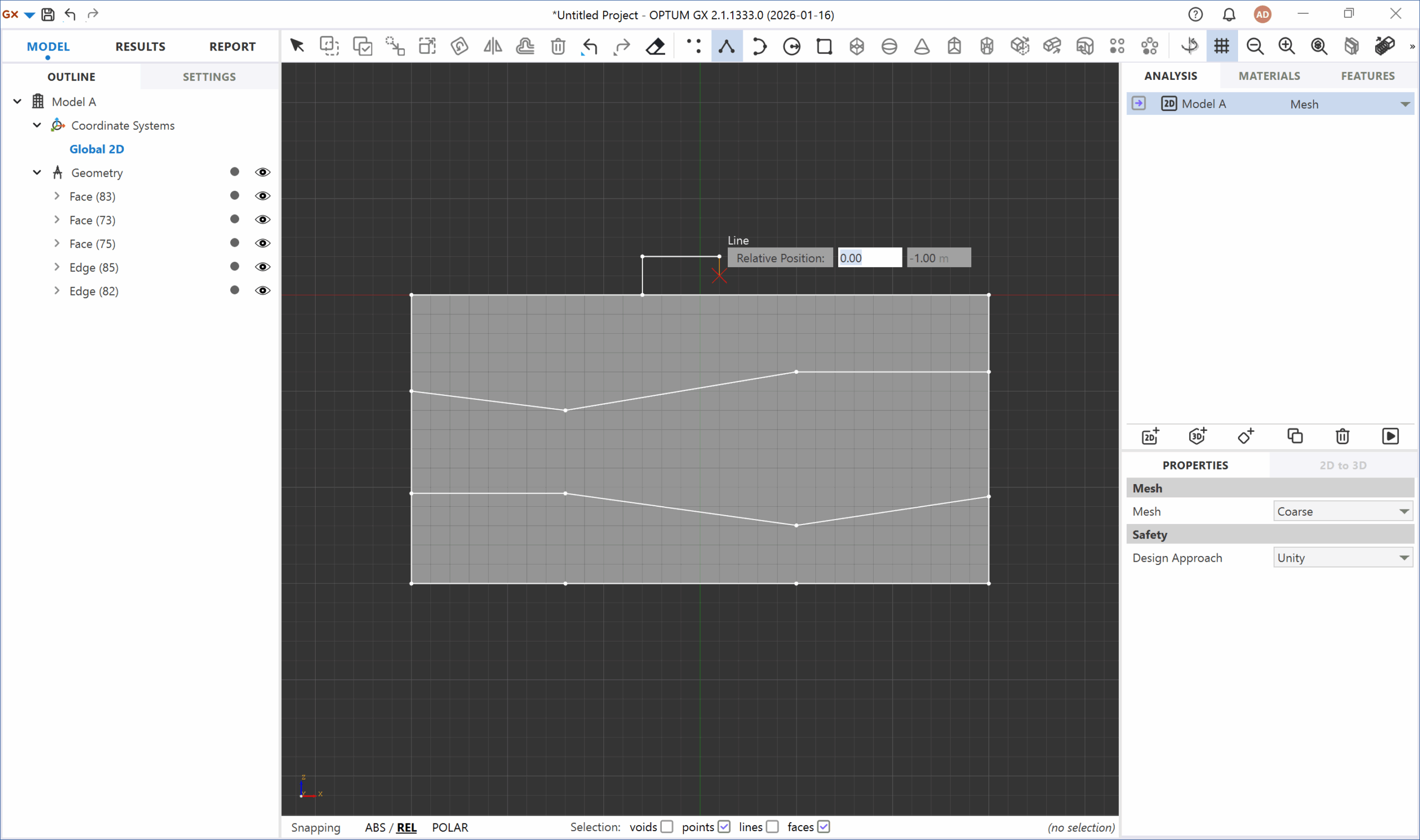
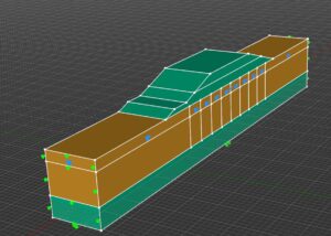
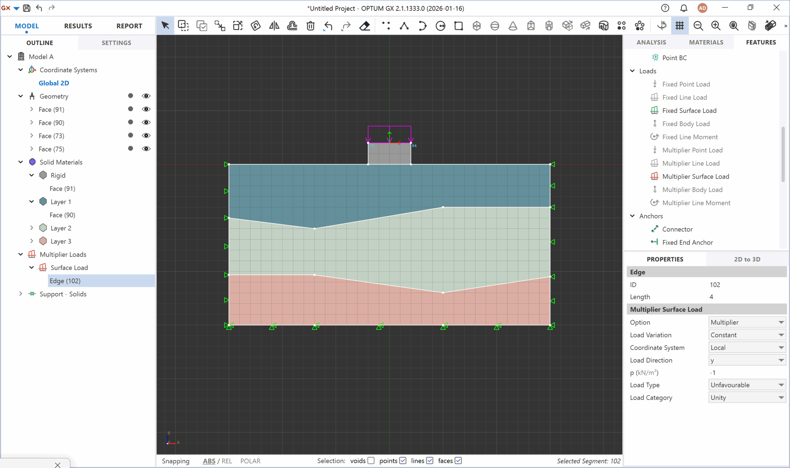
1. Pre-Processing: Geometry and Meshing
Engineers begin by defining the geometry — either drawn directly in the software or imported from CAD.
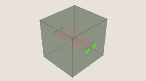
The model is then subdivided into discrete finite elements using a mesh. Mesh quality strongly affects accuracy, especially in areas with high stress gradients or complex geometry.
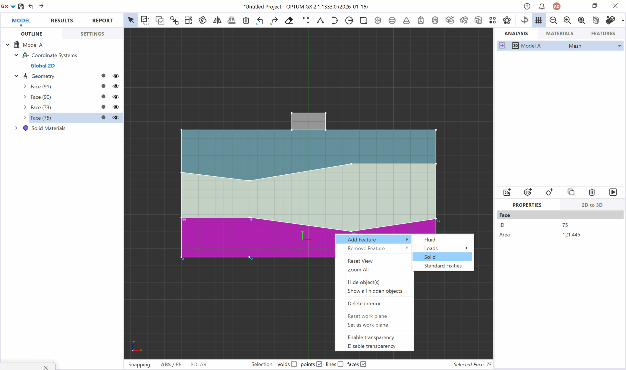
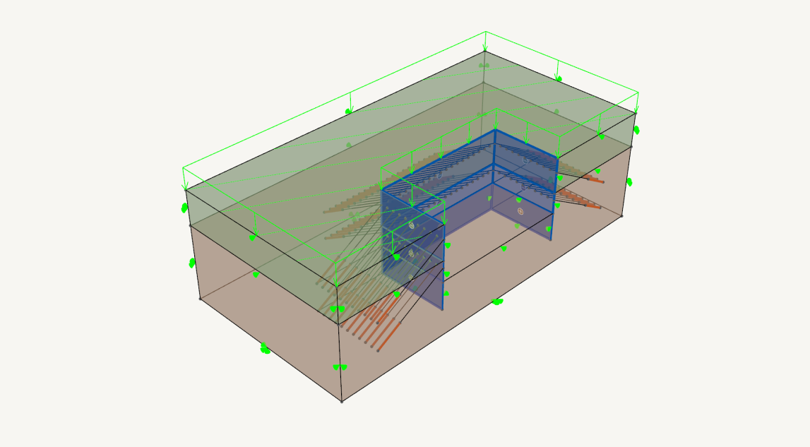
2. Material Properties and Boundary Conditions
Each element is assigned material behaviour (elastic, elastoplastic, nonlinear, thermal, etc.). Supports, loads and constraints define how the structure interacts with its surroundings — a critical step for realistic results.
3. Solving: Assembling and Computing
The solver assembles a global system of equations representing the combined behaviour of all elements.
Depending on the problem, this may involve thousands to millions of unknowns. Modern solvers compute the response efficiently, even for large deformation and nonlinear material behaviour.
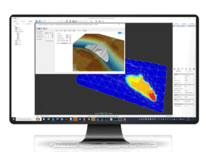
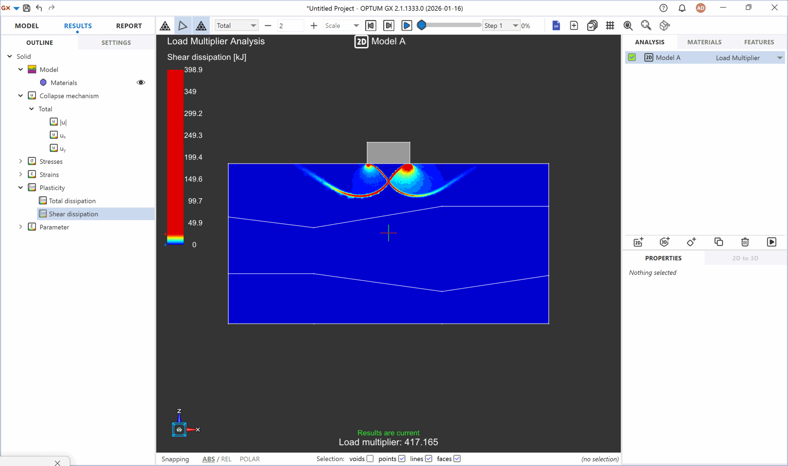
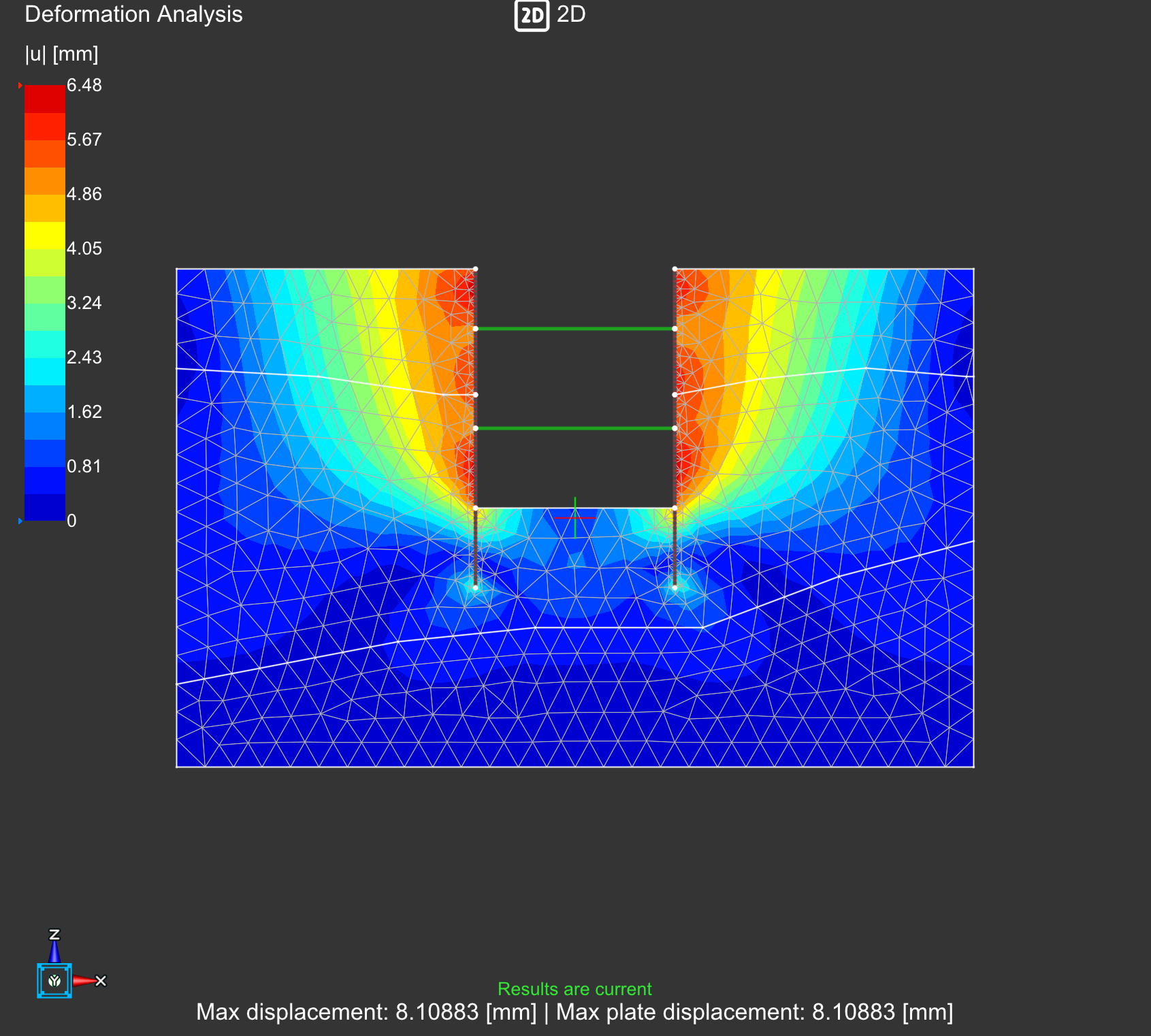
4. Post-Processing: Results and Validation
Engineers visualise stress fields, deformation patterns, safety factors, strains and pore pressures. Results are validated against experience, guidelines or physical testing to ensure the model reflects real-world behaviour.
Key Applications of FEA
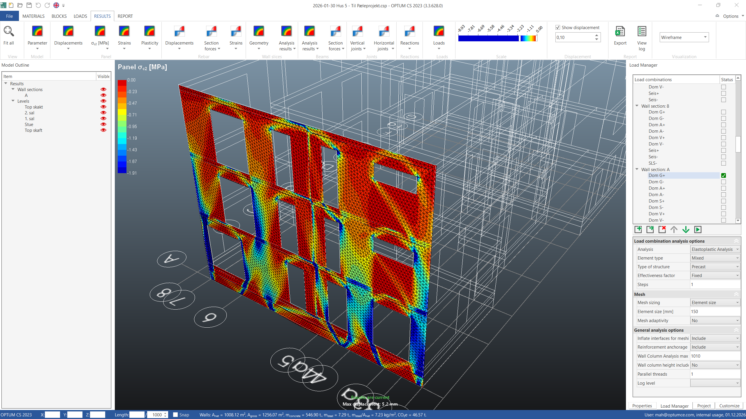
Structural And Civil Engineering
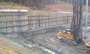
FEA is used to analyse buildings, bridges, retaining structures and foundations — helping engineers understand load paths, deflections and safety margins.
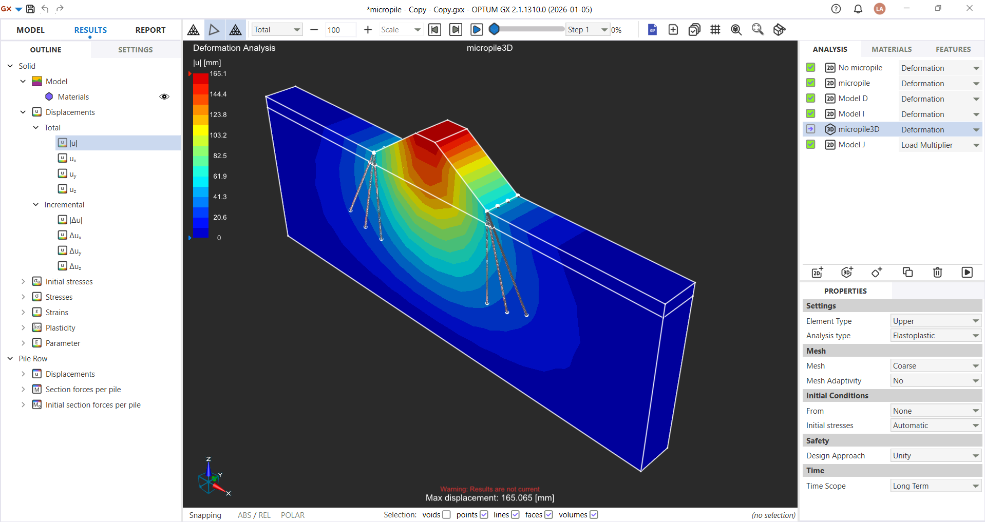
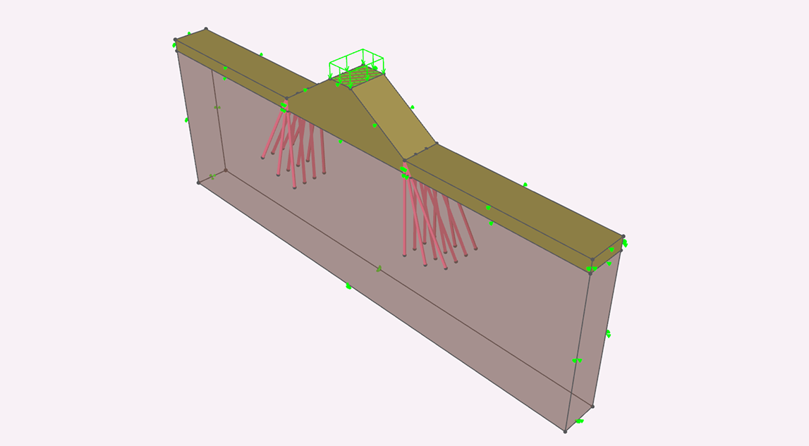
Geotechnical Engineering
Soil is nonlinear, heterogeneous and difficult to model analytically.
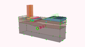
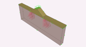
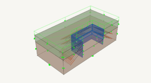
FEA enables reliable assessment of slope stability, retaining walls, tunnels, excavation staging, groundwater interaction and soil–structure interaction.
Benefits and Limitations of FEA
Benefits
Predicts complex behaviour with high accuracy
Reduces physical prototyping and testing costs
Optimises material usage and improves safety
Enables rapid design iterations with modern solvers
Provides deep insight into stresses, deformation and stability
Limitations
- Accuracy depends on mesh quality and correct boundary conditions
- Nonlinear soil behaviour increases computational demands
- Requires engineering judgement in choosing material models and loads
- Conventional FEM solvers may suffer from convergence issues
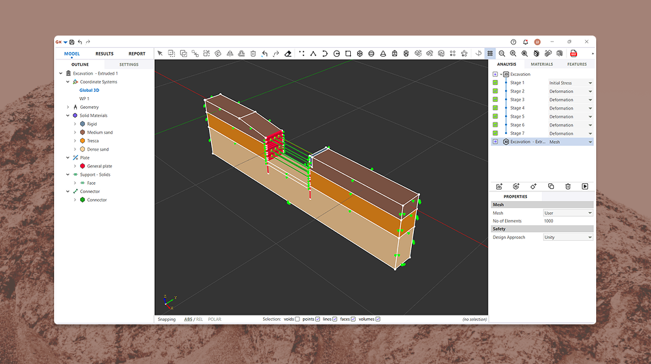
Why OPTUM GX Elevates FEA in Geotechnics
Traditional FEM solvers often struggle with convergence problems, mesh sensitivity and iterative elastoplastic stepping — especially in geotechnical modelling, where soil behaviour is highly nonlinear.
OPTUM GX avoids these challenges entirely through an Optimisation-Based Finite Element Method (OBFEM), providing:

A stable, robust solver for ULS/SLS without iterative load stepping
Integrated 2D and 3D modelling in one environment — no duplicated models
Built-in staged construction, groundwater flow and nonlinear soil models
Instant PDF reporting with plots, tables and documentation
Python automation for parametric studies and batch simulations
The result is a faster, more transparent and more reliable FEA workflow — tailored specifically for soil, rock and soil–structure interaction.
Automating Pre-Processing with Python
With OPTUM GX, pre-processing can even be automated through JORD — our natural-language Python module that converts plain English descriptions into geometry, materials and full analysis scripts.
This removes much of the traditional manual setup and allows engineers to focus on interpreting results rather than constructing models from scratch.

Try OPTUM GX Free
Ready to apply finite element analysis with confidence?
Download OPTUM GX’s free trial or request a personalised walkthrough.
Frequently ASked Questions
Can’t find what you’re looking for? Contact us here.

What is Finite Element Analysis?
February 3, 2026
Finite element analysis (FEA) is a numerical method that breaks a complex structure into many small “elements” to predict how it responds to loads, deformation, temperature changes and other physical...
FEA
Finite element analysis
Geotechnical
OPTUM GX
Micropile Design Software – FEM-Based Analysis in OPTUM GX
January 16, 2026
Micropile design software helps engineers analyse and assess small-diameter drilled piles(micropiles) used where access is restricted, ground conditions are challenging, or high loads mustbe transferred to deeper strata. Typical applications...
FEM
Geotechnical
load transfer
OPTUM GX
Parametric studies
settlement analysis
Sheet pile
Sheet Pile Design Software – FEM-Based Analysis in OPTUM GX
January 13, 2026
Sheet pile design software enables engineers to model, analyse, and assess interlocking sheet pile wall systems used for earth and water retention projects. Typical applications include deep excavations, cofferdams, quay...
Deformation
Excavations
Geotechnical
OPTUM GX
Retaining wall
Seepage
Sheet pile
Staged Construction